
Ceramic capacitors are known to comprise alternating layers of inner electrodes and ceramic dielectrics. A laminated ceramic capacitor includes a laminate formed of a plurality of laminated dielectric ceramic layers and an internal electrode laminated therein. Monolithic ceramic capacitors have a rectangular shape, and are provided with external electrodes at the opposite ends thereof, respectively. The development of integrated circuits has made it possible to place many circuit elements in a single semiconductor chip. A multilayer ceramic capacitor has been used widely as a compact, high power, and highly reliable electronic part and employed in a large number of electronic circuits. The multilayer ceramic capacitor comprises a layered dielectric body composed by alternately laminating dielectric layers and inner electrode layers and terminal electrodes formed on the main body of the layered dielectric element. The ceramic layers are stacked together in a manner that the internal electrodes are alternately exposed at opposite sides of the laminated body. The external electrodes are disposed at the end portions including the opposite sides of the laminated body and are connected to respective sets of internal electrodes of the laminated body.
- 0Commentary
- Tags:
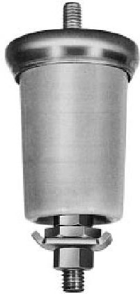
Kt Kingtronics Surge Arresters Protective Gaps
11 Apr 2011Protective gaps are auxiliary devices which serve two purposes: (1) they isolate electrical equipment during normal service conditions, and (2) they provide a path to ground for surge current during arrester operations. Protective gaps used for interconnection of arrester ground, secondary neutral, and transformer tank provide additional protection to distribution transformers and improve continuity of service to customers. Protective gaps provide effective and inexpensive surge protection for the primary neutral of a system (grounded only at the substation) if the potential of the primary neutral is less than 350 volts (rms) above ground. Transformer tanks can be isolated from ground under normal conditions by connecting the transformer to ground through a protective gap.
- 0Commentary
- Tags:
Kt Kingtronics the chose of MLCC Capacitors
4 Apr 2011For a 10uF capacitor we recommend using a 1206 footprint, and for 22uF and 47uF we recommend a 1210 footprint. The 1812 footprint is slightly better than the 1210 for the 47uF, but we don’t think the improvement is worth the extra space and added cost.
Sometimes the product cost may also impact the chosen footprint. For example, if a 1210, 22uF capacitor is more than double the cost of a 1206, then the 1206 component may be preferred. In other applications, the designer may just want to get the maximum capacitance in a limited available footprint. If, for example, there is only room for a 1206 capacitor, the 47uF part will still have the most capacitance even if it loses a larger percentage of its value than the 22uF or the 10uF parts.
- 0Commentary
- Tags:
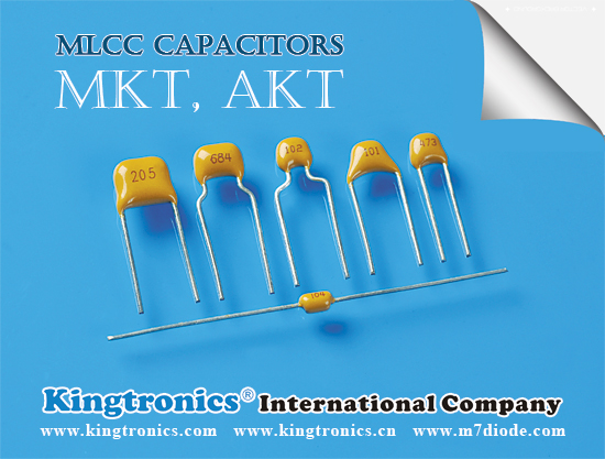
Kt Kingtronics Multilayer Ceramic Capacitor
2 Apr 2011MLCC consists of a conducting material and electrodes. To manufacture a chip-type SMT and achieve miniaturization, high density and high efficiency, ceramic condensers are used. WTC’s MLCC is made by NPO, X7R and Y5V dielectric material and which provides product with high electrical precision, stability and reliability.
For chip multilayer ceramic capacitors, Kt Kingtronics offer size from 0402, 0603, 0805, 1206, 1210, 1808, 1812, 2210, 2225, voltage from 10V to 5000V, dielectric materials include NPO, X7R, Y5V.
Features:
- A wide selection of sizes is available
- High capacitance in given case size.
- Capacitor with lead-free termination (pure Tin).
Applications:
- For general digital circuit.
- For power supply bypass capacitors.
- For consumer electronics.
- For telecommunication.
We supply various electronic components and welcome your inquiry
- 0Commentary
- Tags:
Kingtronics chose of MLCC Capacitor
14 Mar 2011Sometimes the product cost may also impact the chosen footprint. For example, if a 1210, 22uF capacitor is more than double the cost of a 1206, then the 1206 component may be preferred. In other applications, the designer may just want to get the maximum capacitance in a limited available footprint. If, for example, there is only room for a 1206 capacitor, the 47uF part will still have the most capacitance even if it loses a larger percentage of its value than the 22uF or the 10uF parts.
- 0Commentary
- Tags:
Kingtronics MLCC Cracking Proble
9 Mar 2011As the dominant capacitor technology in terms of component quantities, the Multilayer Ceramic Chip Capacitor’s (MLCC) popularity with circuit designers is principally due to its high reliability record and low cost. However, due to the nature of ceramic material the MLCC body can be liable to cracking if mishandled during assembly or used in extreme environments. For this reason cracking in an MLCC body is the most common mode of failure for PCB mounted MLCC components.
- 0Commentary
- Tags:
Kingtronics Use of MLCC Capacitors
5 Mar 2011Multi-layer ceramic chip (MLCC) capacitors are used quite often in dc-dc converter input and output filters. They have low ESR, low ESL, and low cost. They also have no major reliability problems associated with them.
All these properties make them suitable for power management applications. There are still, however, some issues to consider when using these capacitors in dc-dc converter circuits. Some ceramic capacitors can lose a lot of their value under certain conditions. This lost capacitance can degrade the transient response of a dc-dc converter, or it can even make the control loop of the converter unstable.
- 0Commentary
- Tags:
A typical application for high capacitance, high voltage capacitors is a bulk filter capacitor shown in Figure 1 in a bipolar transistor totem pole configuration high voltage, high capacitance MLCCs are commonly used as input capacitor filters.
To obtain the required capacitance and high voltage rating the MLCCs are often placed in parallel or stacked vertically. This requires careful soldering and attachment processing, due to the larger case sizes required for the application. The basic function of the input capacitor filter is to hold up the rectified power bus line voltage as well as for filtering common mode noise.
Common mode noise flows asymmetrically through both input lines. The current into the load is supplied by the input filter capacitor bank rather than from the power supply, until the point at which the input voltage again equals the voltage across the filter capacitor, see wave forms in Figure 2.
- 0Commentary
- Tags:
The fundamental electrical properties of multilayer ceramic capacitors are as follows:
Polarity: Multilayer ceramic capacitors are not polar, and may be used with DC voltage applied in either direction.
Rated Voltage: This term refers to the maximum con tinuous DC working voltage permissible across the entire operating temperature range. Multilayer ceramic capacitors are not extremely sensitive to voltage, and brief applications of voltage above rated will not result in immediate failure. However, reliability will be reduced by exposure to sustained voltages above rated.
Like all other practical capacitors, multilayer ceramic capacitors also have resistance and inductance. A simplified schematic for the equivalent circuit is shown in Figure 1. Other significant electrical characteristics resulting from these additional properties are as follows:

Impedance: Since the parallel resistance (Rp) normally very high, the total impedance of the capacitor is :
The variation of a capacitor’s impedance with frequency determines its effectiveness in many applications.
- 0Commentary
- Tags:Kt kingtronics Multilayer Ceramic Capacitors Axial Multilayer Ceramic Capacitors Chip multilayer ceramic capacitors MKT-Radial Multilayer Ceramic Capacitors MLCC Multilayer Ceramic Capacitors Radial multilayer ceramic capacitors General Electrical Characteristics Polarity rated voltage resistance
MLCC consists of a conducting material and electrodes. To manufacture a chip-type SMT and achieve miniaturization, high density and high efficiency, ceramic condensers are used.
WTC’s MLCC is made by NPO, X7R and Y5V dielectric material and which provides product with high electrical precision, stability and reliability.
Storage and Operating Condition
(1) To store products at 5℃ to 40℃ ambient temperature and 20% to 70%. related humidity conditions.
(2) The product is recommended to be used within one year after shipment. Check solderability in case of shelf life extension is needed.
Cautions:
a. Don’t store products in a corrosive environment such as sulfide, chloride gas, or acid. It may cause oxidization of electrode, which easily be resulted in poor soldering.
b. To store products on the shelf and avoid exposure to moisture.
c. Don’t expose products to excessive shock, vibration, direct sunlight and so on.
Contact us
Tel: (86) 769 8118 8110
Tel: (852) 8106 7033
Fax: (852) 8106 7099
E-mail: info@kingtronics.com
Skype: kingtronics.sales
MSN: kingtronics-sales@hotmail.com
Web: www.Kingtronics.com
YouTube: www.youtube.com/c/Kingtronicskt
About
Kingtronics International Company was established in 1995 located in Dongguan City of China to handle all sales & marketing for factories located in Chengdu, Sichuan and Zhaoqing, Guangdong, China. In 1990, we established the first factory to produce trimming potentiometer and in 1999 we built up new factory in Zhao Qing, Guangdong. Now with around 850 workers, Kingtronics produce trimming potentiometers, dipped tantalum capacitors, multilayer ceramic capacitors, and diode & bridge rectifier. We sell good quality under our brand Kingtronics, and Kt, King, Kingtronics are our three trademarks. All our products are RoHS compliant, and our bridge rectifier have UL approval. Please visit our Products page, you could please download all our PDF datasheet and find cross reference for our Trimming Potentiometer and capacitors.
Tantalum and Ceramic Capacitors Cross Reference ↓ Download
Diodes & Rectifiers List(PDF: 97KB) ↓ Download
Trimming Potentiometer Cross Reference ↓Download
Categories
 Kt Kingtronics (245)
- Diodes & Rectifiers (160)
- Aluminum Electrolytic Capacitor (149)
- Trimming Potentiometers (123)
- Tantalum Capacitors (94)
- Multilayer Ceramic Capacitors (70)
- Kt Bridge Rectifier (64)
- Quartz Crystals (58)
- Surge Arresters (34)
- Tactile Switches (32)
- Kt Kingtronics Components (30)
- Ceramic Trimmer Capacitors (25)
- Film Capacitors (23)
- Super Capacitors (17)
- Metal Oxide Varistor (10)
- Negative Temperature Coefficient Thermistor (6)
- Music capacitors (2)
Archives
- 2024 April (3)
- 2024 March (2)
- 2024 February (2)
- 2024 January (3)
- 2023 December (1)
- 2023 November (2)
- 2023 October (1)
- 2023 September (2)
- 2023 August (2)
- 2023 July (4)
- 2023 June (12)
- 2023 May (6)
- 2023 April (4)
- 2023 March (3)
- 2023 February (2)
- 2023 January (1)
- 2022 December (3)
- 2022 November (2)
- 2022 October (3)
- 2022 September (4)
- 2022 August (3)
- 2022 July (3)
- 2022 June (2)
- 2022 May (3)
- 2022 April (4)
- 2022 March (4)
- 2022 February (2)
- 2022 January (3)
- 2021 December (4)
- 2021 November (3)
- 2021 October (4)
- 2021 September (4)
- 2021 August (4)
- 2021 July (4)
- 2021 June (5)
- 2021 May (4)
- 2021 April (3)
- 2021 March (4)
- 2021 February (4)
- 2021 January (4)
- 2020 December (5)
- 2020 November (4)
- 2020 October (4)
- 2020 September (7)
- 2020 August (8)
- 2020 July (9)
- 2020 June (8)
- 2020 May (9)
- 2020 April (11)
- 2020 March (6)
- 2020 February (4)
- 2020 January (4)
- 2019 December (6)
- 2019 November (7)
- 2019 October (6)
- 2019 September (5)
- 2019 August (9)
- 2019 July (6)
- 2019 June (4)
- 2019 May (16)
- 2019 April (6)
- 2019 March (6)
- 2019 February (9)
- 2019 January (5)
- 2018 December (4)
- 2018 November (4)
- 2018 October (5)
- 2018 September (8)
- 2018 August (10)
- 2018 July (7)
- 2018 June (12)
- 2018 May (22)
- 2018 April (4)
- 2018 March (4)
- 2018 February (8)
- 2018 January (13)
- 2017 December (4)
- 2017 November (4)
- 2017 October (5)
- 2017 September (4)
- 2017 August (21)
- 2017 July (7)
- 2017 June (5)
- 2017 May (4)
- 2017 April (4)
- 2017 March (9)
- 2017 February (8)
- 2017 January (8)
- 2016 December (10)
- 2016 November (16)
- 2016 October (8)
- 2016 September (10)
- 2016 August (13)
- 2016 July (12)
- 2016 June (10)
- 2016 May (14)
- 2016 April (8)
- 2016 March (10)
- 2016 February (6)
- 2016 January (8)
- 2015 December (10)
- 2015 November (8)
- 2015 October (3)
- 2015 July (5)
- 2015 June (9)
- 2015 May (7)
- 2015 April (8)
- 2015 March (9)
- 2015 February (7)
- 2015 January (5)
- 2014 December (13)
- 2014 November (4)
- 2014 October (4)
- 2014 September (5)
- 2014 August (4)
- 2014 July (4)
- 2014 June (4)
- 2014 May (4)
- 2014 April (4)
- 2014 March (5)
- 2014 February (3)
- 2014 January (4)
- 2013 December (8)
- 2013 November (9)
- 2013 October (10)
- 2013 September (9)
- 2013 August (11)
- 2013 July (10)
- 2013 June (3)
- 2013 May (4)
- 2013 April (5)
- 2013 March (2)
- 2013 February (1)
- 2013 January (3)
- 2012 December (5)
- 2012 November (6)
- 2012 October (5)
- 2012 September (10)
- 2012 August (11)
- 2012 July (11)
- 2012 June (12)
- 2012 May (14)
- 2012 April (10)
- 2012 March (14)
- 2012 February (10)
- 2012 January (6)
- 2011 December (9)
- 2011 November (11)
- 2011 October (10)
- 2011 September (13)
- 2011 August (14)
- 2011 July (13)
- 2011 June (13)
- 2011 May (13)
- 2011 April (14)
- 2011 March (27)
- 2011 February (13)
- 2011 January (24)
- 2010 December (21)
- 2010 November (12)
- 2010 October (11)