
Kt Kingtronics Surge Arresters
23 Mar 2011Surge Arresters conduct lightning surges around the protected insulator so that a lightning flashover is not created. They are designed to be installed functionally in parallel with the line insulator. The arrester conducts the lightning surges around the protected insulator so that a subsequent 60 Hz fault on the circuit is not created. The arrester becomes a low ohmic path for the surge as voltage across it increases. When the voltage returns to normal, the arrester once again returns to a high ohmic device with only microamps of leakage current.
If an arrester experiences a surge higher than it is capable of handling without failure, and it is failure, equipped with an isolating device, it will isolating device, disconnect during the event.
After the surge is over, and fault current starts to flow, the disconnector senses the fault and ignites the powder built into the device.
The disconnecting device is not an interrupter so during this rare event, an interrupting device must clear the circuit.
- 0Commentary
- Tags:
Kt Kingtronics Trademark
22 Mar 2011Kingtronics supply series kinds of Capacitors and Diodes .All this products are sighed in our Kt Trademark, For the Kt Kingtronics trademark, We can give you the first class service. Because Kt Kingtronics has the following Strength and Advantage:
Kt Kingtronis has High quality commitment
Well-known brand Kt Kingtronics
Kt Kingtronics can provide Competitive prices
Kt Kingtronics provide Fast lead time & stock
Kt Kingtronics has Strong sales support
Kt Kingtronics ‘s Sales response quickly
Kt Kingtronics has Strong technical support
Kt Kingtronics has Excellent customer service
Kt Kingtronics Exhibitions overseas
- 0Commentary
- Tags:
Kt Kingtronics Diode Bridge Rectifier
21 Mar 2011A diode bridge is an arrangement of four (or more) diodes in a bridge configuration that provides the same polarity of output for either polarity of input. When used in its most common application, for conversion of an alternating current (AC) input into direct current a (DC) output, it is known as a bridge rectifier. A bridge rectifier provides full-wave rectification from a two-wire AC input, resulting in lower cost and weight as compared to a rectifier with a 3-wire input from a transformer with a center-tapped secondary winding.
The essential feature of a diode bridge is that the polarity of the output is the same regardless of the polarity at the input. The diode bridge circuit is also known as the Graetz circuit after its inventor, physicist Leo Graetz.
In actuality, free electrons in a conductor nearly always flow from the negative to the positive pole. In the vast majority of applications, however, the actual direction of current flow is irrelevant. Therefore, in the discussion below the conventional model is retained.
Prior to the availability of integrated circuits, a bridge rectifier was constructed from "discrete components", i.e., separate diodes. Since about 1950, a single four-terminal component containing the four diodes connected in a bridge configuration became a standard commercial component and is now available with various voltage and current ratings.
For many applications, especially with single phase AC where the full-wave bridge serves to convert an AC input into a DC output, the addition of a capacitor may be desired because the bridge alone supplies an output of fixed polarity but continuously varying or "pulsating" magnitude, an attribute commonly referred to as "ripple".
- 0Commentary
- Tags:
Kingtronics Surge Arrester
19 Mar 2011The valve arrester consists of disks of zinc oxide material that exhibit low resistance at high voltage and high resistance at low voltage. By selecting an appropriate configuration of disk material, the arrester will conduct a low current of a few milliamperes at normal system voltage. During conditions of lightning or switching surge over voltage, the surge current is limited by the circuit; and for the magnitudes of current that can be delivered to the arrester location, the resulting voltage will be limited to controlled values, and to safe levels as well, when insulation levels of equipment are coordinated with the surge arrester protective characteristics.
A typical surge arrester consists of disks of zinc oxide material sized in cross-sectional area to provide desired energy discharge capability, and in axial length proportional to the voltage capability. The disks are then placed in porcelain enclosures to provide physical support and heat removal, and sealed for isolation from contamination in the electrical environment.
- 0Commentary
- Tags:
To analyse the electrical response of a quartz crystal resonator, it is very often useful to depict it as the equivalent electrical components that would be needed to replace it. This equivalent circuit is can then be used to analyse its response and predict its performance. The basic equivalent circuit of a crystal is shown below. In this circuit C1 represents the capacitance between the electrodes. L, C, and R represent the vibrational characteristics of the crystal. The inductance results from the mass of the material, C from the compliance, and R arises from the losses of which the greatest contributor is frictional losses.
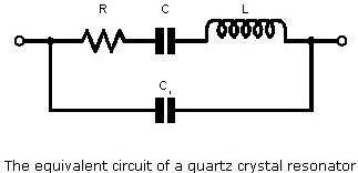
Looking at this circuit it can be seen that there are two ways in which the circuit can resonate. One is from the resonance of L and C which provides a series resonance, giving a very low value of impedance at resonance. This is determined by the value of the resistance R. In this mode the external circuit has very little effect on the crystal resonance.
- 0Commentary
- Tags:
Schottky Rectifiers have been used in the power supply industry for approximately 15 years. During this time, significant fiction as well as fact has been associated with this type of rectifier. The primary assets of Schottky devices are switching speeds approaching zero-time and very low forward voltage drop (VF). This combination makes Schottky barrier rectifiers ideal for the output stages of switching power supplies. On the negative side, Schottky devices are also known for limited high-temperature operation, high eakage and limited voltage range BVR. Though these limitations exist, they are quantifiable and controllable, allowing wide application of these devices in switch mode power supplies.
- 0Commentary
- Tags:
Kingtronics Zener Diodes Function
16 Mar 2011Zener diodes regulate voltage by acting as complementary loads, drawing more or less current as necessary to ensure a constant voltage drop across the load. This is analogous to regulating the speed of an automobile by braking rather than by varying the throttle position: not only is it wasteful, but the brakes must be built to handle all the engine's power when the driving conditions don't demand it. Despite this fundamental inefficiency of design, zener diode regulator circuits are widely employed due to their sheer simplicity. In high-power applications where the inefficiencies would be unacceptable, other voltage-regulating techniques are applied. But even then, small zener-based circuits are often used to provide a “reference” voltage to drive a more efficient amplifier circuit controlling the main power.
- 0Commentary
- Tags:
Kt Kingtronics Polarity for Tantalum Capacitor
15 Mar 2011Tantalum Capacitors are inherently polar devices and may be permanently damaged or destroyed if connected with the wrong polarity. The positive terminal is identified on the capacitor body by a polarity mark and the capacitor body may include an obvious geometrical shape.
However, some Series contain two capacitors connected (negative-to-negative) to form “non-polar” capacitors. Rated voltage may be applied to these Series in either direction.
Kingtronics chose of MLCC Capacitor
14 Mar 2011Sometimes the product cost may also impact the chosen footprint. For example, if a 1210, 22uF capacitor is more than double the cost of a 1206, then the 1206 component may be preferred. In other applications, the designer may just want to get the maximum capacitance in a limited available footprint. If, for example, there is only room for a 1206 capacitor, the 47uF part will still have the most capacitance even if it loses a larger percentage of its value than the 22uF or the 10uF parts.
- 0Commentary
- Tags:
Kt Kingtronics Use of Tantalum Capacitor
12 Mar 2011The low leakage and high capacity of tantalum capacitors favors their use in sample and hold circuits to achieve long hold duration, and some long duration timing circuits where precise timing is not critical. They are also often used for power supply rail decoupling in parallel with film or ceramic capacitors with low ESR and reactance at high frequency. Tantalum capacitors can replace aluminum electrolytic capacitors in situations where the external environment or dense component packing results in a sustained hot internal environment and where high reliability is important. Equipment such as medical electronics and space equipment that require high quality and reliability make use of tantalum capacitors.
Low-voltage tantalum capacitors are commonly used in large numbers for power supply filtering on computer motherboards and in peripherals due to their small size and long-term reliability.

Contact us
Tel: (86) 769 8118 8110
Tel: (852) 8106 7033
Fax: (852) 8106 7099
E-mail: info@kingtronics.com
Skype: kingtronics.sales
MSN: kingtronics-sales@hotmail.com
Web: www.Kingtronics.com
YouTube: www.youtube.com/c/Kingtronicskt
About
Kingtronics International Company was established in 1995 located in Dongguan City of China to handle all sales & marketing for factories located in Chengdu, Sichuan and Zhaoqing, Guangdong, China. In 1990, we established the first factory to produce trimming potentiometer and in 1999 we built up new factory in Zhao Qing, Guangdong. Now with around 850 workers, Kingtronics produce trimming potentiometers, dipped tantalum capacitors, multilayer ceramic capacitors, and diode & bridge rectifier. We sell good quality under our brand Kingtronics, and Kt, King, Kingtronics are our three trademarks. All our products are RoHS compliant, and our bridge rectifier have UL approval. Please visit our Products page, you could please download all our PDF datasheet and find cross reference for our Trimming Potentiometer and capacitors.
Tantalum and Ceramic Capacitors Cross Reference ↓ Download
Diodes & Rectifiers List(PDF: 97KB) ↓ Download
Trimming Potentiometer Cross Reference ↓Download
Categories
 Kt Kingtronics (245)
- Diodes & Rectifiers (160)
- Aluminum Electrolytic Capacitor (149)
- Trimming Potentiometers (123)
- Tantalum Capacitors (94)
- Multilayer Ceramic Capacitors (70)
- Kt Bridge Rectifier (64)
- Quartz Crystals (58)
- Surge Arresters (34)
- Tactile Switches (32)
- Kt Kingtronics Components (30)
- Ceramic Trimmer Capacitors (25)
- Film Capacitors (23)
- Super Capacitors (17)
- Metal Oxide Varistor (10)
- Negative Temperature Coefficient Thermistor (6)
- Music capacitors (2)
Archives
- 2024 April (3)
- 2024 March (2)
- 2024 February (2)
- 2024 January (3)
- 2023 December (1)
- 2023 November (2)
- 2023 October (1)
- 2023 September (2)
- 2023 August (2)
- 2023 July (4)
- 2023 June (12)
- 2023 May (6)
- 2023 April (4)
- 2023 March (3)
- 2023 February (2)
- 2023 January (1)
- 2022 December (3)
- 2022 November (2)
- 2022 October (3)
- 2022 September (4)
- 2022 August (3)
- 2022 July (3)
- 2022 June (2)
- 2022 May (3)
- 2022 April (4)
- 2022 March (4)
- 2022 February (2)
- 2022 January (3)
- 2021 December (4)
- 2021 November (3)
- 2021 October (4)
- 2021 September (4)
- 2021 August (4)
- 2021 July (4)
- 2021 June (5)
- 2021 May (4)
- 2021 April (3)
- 2021 March (4)
- 2021 February (4)
- 2021 January (4)
- 2020 December (5)
- 2020 November (4)
- 2020 October (4)
- 2020 September (7)
- 2020 August (8)
- 2020 July (9)
- 2020 June (8)
- 2020 May (9)
- 2020 April (11)
- 2020 March (6)
- 2020 February (4)
- 2020 January (4)
- 2019 December (6)
- 2019 November (7)
- 2019 October (6)
- 2019 September (5)
- 2019 August (9)
- 2019 July (6)
- 2019 June (4)
- 2019 May (16)
- 2019 April (6)
- 2019 March (6)
- 2019 February (9)
- 2019 January (5)
- 2018 December (4)
- 2018 November (4)
- 2018 October (5)
- 2018 September (8)
- 2018 August (10)
- 2018 July (7)
- 2018 June (12)
- 2018 May (22)
- 2018 April (4)
- 2018 March (4)
- 2018 February (8)
- 2018 January (13)
- 2017 December (4)
- 2017 November (4)
- 2017 October (5)
- 2017 September (4)
- 2017 August (21)
- 2017 July (7)
- 2017 June (5)
- 2017 May (4)
- 2017 April (4)
- 2017 March (9)
- 2017 February (8)
- 2017 January (8)
- 2016 December (10)
- 2016 November (16)
- 2016 October (8)
- 2016 September (10)
- 2016 August (13)
- 2016 July (12)
- 2016 June (10)
- 2016 May (14)
- 2016 April (8)
- 2016 March (10)
- 2016 February (6)
- 2016 January (8)
- 2015 December (10)
- 2015 November (8)
- 2015 October (3)
- 2015 July (5)
- 2015 June (9)
- 2015 May (7)
- 2015 April (8)
- 2015 March (9)
- 2015 February (7)
- 2015 January (5)
- 2014 December (13)
- 2014 November (4)
- 2014 October (4)
- 2014 September (5)
- 2014 August (4)
- 2014 July (4)
- 2014 June (4)
- 2014 May (4)
- 2014 April (4)
- 2014 March (5)
- 2014 February (3)
- 2014 January (4)
- 2013 December (8)
- 2013 November (9)
- 2013 October (10)
- 2013 September (9)
- 2013 August (11)
- 2013 July (10)
- 2013 June (3)
- 2013 May (4)
- 2013 April (5)
- 2013 March (2)
- 2013 February (1)
- 2013 January (3)
- 2012 December (5)
- 2012 November (6)
- 2012 October (5)
- 2012 September (10)
- 2012 August (11)
- 2012 July (11)
- 2012 June (12)
- 2012 May (14)
- 2012 April (10)
- 2012 March (14)
- 2012 February (10)
- 2012 January (6)
- 2011 December (9)
- 2011 November (11)
- 2011 October (10)
- 2011 September (13)
- 2011 August (14)
- 2011 July (13)
- 2011 June (13)
- 2011 May (13)
- 2011 April (14)
- 2011 March (27)
- 2011 February (13)
- 2011 January (24)
- 2010 December (21)
- 2010 November (12)
- 2010 October (11)